自平衡荷载箱Super-Cell制造、研发和技术服务
info@ougangroup.comPile Shaft Stress Testing
1. Strain gauge installation and embedment
(1) Select strain gauge according to reinforcement bar diameter, and if there is no exact size of strain gauge, similar one is also ok. Strain gauges are
embedded in different soil layer to measure the pile skin friction in different soil layer.
(2) Screw down the strain gauge (with cable) with connecting bars by pipe wrench, adhesive tape can be used to cover connection. Then weld
gauge to rebar of the same size. It is important to cool the sensor part by watering or wet cloth to avoid the damage of sensor due to high temperature
during welding.
(3) Install 3 strain gauges in each section of different soil layer, to measure the skin friction of pile in different soil layer. So rebars with 3 well-distributed positions should be reserved in reinforcement cage fabrication, and these rebars will be welded to cage after strain gauge welding.
Or rebars in these corresponding positions are cut after cage fabrication to weld strain gauges.
Sketch of strain gauge welding and cable fix:

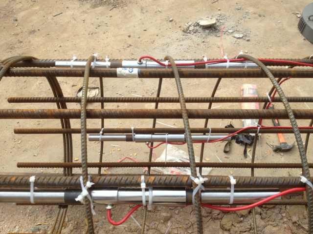
Picture of strain gauge cable fixing
2. Pile shaft stress test and calculation
(1) When vibrating strain gauge is applied, actual frequency of strain gauge will be converted to force through calibration coefficient,
and rebar strain equivalent to concrete strain in strain gauge section will be calculated.
(2) In the process of data handling, testing points which are with big zero-drift, or irregular variation should be deleted, and average
strain of effective testing points in same cross-section is calculated to get pile shaft axial load in same section by following formula:

Qi——Axial load of No. i section of pile shaft (kN);
 ——Average strain of No. i section;
Ei ——Pile shaft material elasticity modulus in section i (kPa);
Ai ——No.i pile shaft section area (m2);
(1) Tabulate the axial load at different section level under each cycle of loading test, and graph distribution diagram. Calculate pile
ultimate skin friction resistance in each soil layer and ultimate end bearing according to axial load in each section under pile top ultimate loading:


qsi—— pile shaft resistance between section i and section i+1(kPa);
qp——pile end bearing (kPa);
i——pile test section No., i=1,2,……,n,small to big from pile top;
u——pile shaft perimeter (m);
li ——pile length between section i and section i+1 (m);
Qn——pile toe axial force (kN);
A0——pile toe area (m2);
